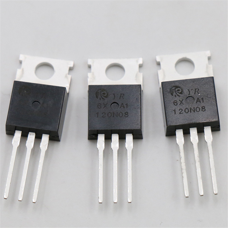


Between these two N+ regions, there occurs diffusion to form an Nchannel, connecting drain and source.Ī thin layer of Silicon dioxide (SiO 2) is grown over the entire surface and holes are made to draw ohmic contacts for drain and source terminals. A lightly doped P-type substrate is taken into which two heavily doped N-type regions are diffused, which act as source and drain. Let us consider an N-channel MOSFET to understand its working. Also, there is no need to mention that the study of one type explains the other too. Usually an NChannel MOSFET is considered for explanation as this one is mostly used. Now, let us go through the constructional details of an N-channel MOSFET. The symbols for P-channel MOSFET are as given below. The P-channel MOSFETs are simply called as PMOS. The symbols for N-channel MOSFET are as given below. The N-channel MOSFETs are simply called as NMOS. Classification of MOSFETsĭepending upon the type of materials used in the construction, and the type of operation, the MOSFETs are classified as in the following figure.Īfter the classification, let us go through the symbols of MOSFET. With negative gate bias voltage, it acts as depletion MOSFET while with positive gate bias voltage it acts as an Enhancement MOSFET. In this case, both positive and negative voltages can be applied on the gate as it is insulated from the channel. The voltage at gate controls the operation of the MOSFET. The following figure shows the construction of a MOSFET. Depending upon the substrate used, they are called as P-type and N-type MOSFETs. In the construction of MOSFET, a lightly doped substrate, is diffused with a heavily doped region. This oxide layer acts as an insulator (sio 2 insulates from the substrate), and hence the MOSFET has another name as IGFET. An oxide layer is deposited on the substrate to which the gate terminal is connected. The construction of a MOSFET is a bit similar to the FET. The following figure shows how a practical MOSFET looks like.

The FET is operated in both depletion and enhancement modes of operation. This is also called as IGFET meaning Insulated Gate Field Effect Transistor. MOSFET stands for Metal Oxide Silicon Field Effect Transistor or Metal Oxide Semiconductor Field Effect Transistor. To overcome these disadvantages, the MOSFET which is an advanced FET is invented. Temperature measurement examples are shown in Figure 3 (1)-(3).FETs have a few disadvantages like high drain resistance, moderate input impedance and slower operation. There are almost no differences in the capacitance characteristics at different temperatures. As V DS increases the capacitance decreases. Generally, all 3 capacitances (C iss,C oss,C rss) listed in Table 1 are included in MOSFET specifications.Īs shown in Figure 2 the capacitance characteristics may depend on V DS (Drain-Source voltage). Cgs and Cgd are the capacitances of the oxide layers, while Cds is determined by the junction capacitance of the internal diode. The silicon under the gate has the opposite polarity to the drain and source which results in the formation of PN junctions (diode) between the Gate, Drain and Source regions.

The Gate terminal in a MOSFET is isolated from the other terminals by an oxide film. Capacitance is the ability of a system to store an electric charge. Sometimes known as stray capacitance, parasitic capacitance is unavoidable and typically unwanted that exists between the parts of an electronic component or circuit simply because of how close they are to one another. Parasitic capacitance exists in power MOSFETs as shown in Figure 1. MOSFET Parasitic Capacitance and Temperature Characteristics Parasitic Capacitance


 0 kommentar(er)
